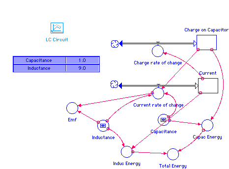
Inductance In Lc Circuit
At all of the energy is stored in the capacitor which has charge c. B what is the maximum current flowing through circuit.

Rlc Series Ac Circuits College Physics

R L C Series Circuits
D P O A X Xm Uy
C how long does it take the capacitor to become completely discharged.

Inductance in lc circuit. When a charged capacitor is allowed to discharge through an resistance less inductor the current oscillates back and forth in the circuit. If you would like to calculate the resonant frequency of an lc circuit look no further this resonant frequency calculator is the tool for you. An audio crossover circuit consisting of three lc circuits each tuned to a different natural frequency is shown to the right.
We already know that capacitance and inductor can store electrical and magnetic energy respectively. The resonant frequency 3559 khz is the same for all lc circuits in the parallel lc circuit the applied voltage is the same for the inductor and a capacitor but the individual currents in both branches of the circuit are. See figure 4 such a circuit is known as an lc circuit for obvious reasons.
This happens at a specific frequency called the resonant frequency. An lc circuit is shown in figure pageindex1. Enter the inductance and capacitance and in no time at all youll find the resonant and angular frequency.
An lc circuit in an lc circuit the self inductance is h and the capacitance is f. D find an equation that represents qt. Lc circuit left consisting of ferrite coil and capacitor used as a tuned circuit in the receiver for a radio clock an lc circuit also called a resonant circuit tank circuit or tuned circuit is an electric circuit consisting of an inductor represented by the letter l and a capacitor represented by the letter c connected together.
If the capacitor contains a charge q0 before the switch is closed then all the energy of the circuit is initially stored in the electric field of the capacitor figure a. An lc circuit is one consisting of a coil and a capacitor that resonate with each other passing energy back and forth between them a circuit is shown below. Consider an electrical circuit consisting of an inductor of inductance connected in series with a capacitor of capacitance.
The inductors l are on the top of the circuit and the capacitors c are on the bottom. A graph of several ideal parallel lc circuits impedance z lc against frequency f for a given inductance and capacitance. The l is the symbol for inductance which is a property of the coil.
On the left a woofer circuit tuned to a low audio frequency on the right a tweeter circuit tuned to a high audio frequency. A what is the angular frequency of the oscillations in the circuit. We start with an idealized circuit of zero resistance that contains an inductor and a capacitor an lc circuit.
Suppose that is the instantaneous current flowing around the circuit. 7 the l c circuit.

Openstax College Physics Solution Chapter 24 Problem 39 Problems Exercises

Working Of Inductor And Capacitor Lc Circuit With A Dc Supply A Graphical Study

Lessons In Electric Circuits Volume Ii Ac Chapter 6

Microstrip Circuits And Equivalent Lc Circuits A

Calctool Rlc Or Lc Circuit Calculator

What Is The Sign Of Voltage Across The Inductor In An Rlc

Lc Circuit Model
D P O A X Xm Uy

Offset Problem In Simulating Current And Voltage Phase

Ppt Self Inductance And Circuits Powerpoint Presentation

Series Rlc Circuit And Rlc Series Circuit Analysis

Physicslab Lc Circuit
Comments
Post a Comment